I was looking for a blinker for my railroad crossing in several model catalogs, but this blinker were antiquated. Some were working with relays. The blinker with electronic components were not much better. It flashes too fast and hard. I found nowhere a blinker, which fades the lights soft on and off, like in the reality. I tried a electronic blinker for 5 DM from a electronic discounter with poor results. I was able to slow down the flashing frequency, but there was still the "hard" flashing. At this time I hat no knowledge about electrnic, but I started to design my own blinker. First I simulate the circuit on my computer with the program Electronics Workbench from ComPro Hard- & Software Vetriebs GmbH. More Infos are on http://www.com-pro.de.
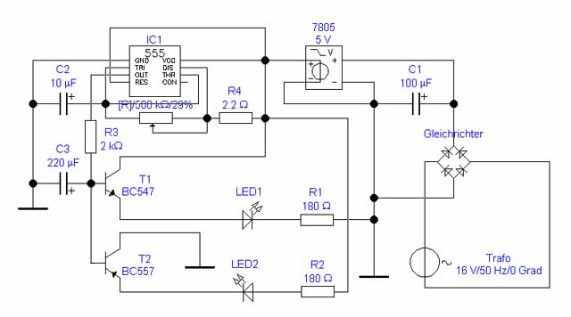
Like shown on the circuit diagram, the blinker can be connected to a Maerklin transformer (16 V AC), a 12 V DC transformer or directly to the Marklin digital power (22 V). The power is converted to DC, softed with the capacitor C1 and reduced to 5 V withe the regulator 7805. On the diagram the 7805 has four pins, but the real ones have only three pins. Ground is the common pin. The heart of the circuit is the timer NE555CN. One pin of it is unused. The flashing frequenzy can be adjust with the 500 kilo ohm potentiometer. A npn transistor BC547C and a pnp transistor BC557C are connected to the output of IC1. The LEDs are connected to the emitter of the transistors. To reduce the power, a 180 ohm resistor (R1 and R2) must be soldered to the LEDs. The capacitor C3 makes the flashing soft.
Pins of the NE555:
1 = GND (ground)
2 = TRI (trigger)
3 = OUT (output)
4 = RES (reset)
5 = CON (control input)
6 = THR (threshold)
7 = DIS (discharge)
8 = VCC (power)
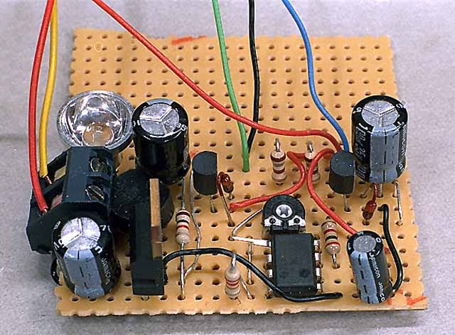
I soldered all components onto an experimentation circuit board. The LED left is only to control the main power and not in the circuit diagram drawn. The first version of the blinker has two diodes 1N4148 before the base of the transistors, but they are useless. The blinker on the photo has still them.
I use the railraod crossing warning signs 5059 from Viessmann. Normaly it has an additional resistor, but for using it with this blinker, it must be removed. The first test was a positive surprise. The red LEDs are flashing very soft, like at a real railroad crossing. The preview of computer simulation shows the same results, but I was happy, that my first electronic experiment works so well.
Components:
experimentation circuit board
1 x IC NE555CN
1 x npn-Transistor BC547C
1 x pnp-Transistor BC557C
1 x DC converter
1 x regulator 7805 (+5 Volt)
1 x capacitor 10 uF
1 x capacitor 100 uF
1 x capacitor 220 uF
1 x potentiometer linear 500 kOhm
2 x resistor 180 Ohm
1 x resistor 2 kOhm
1 x resistor 2,2 kOhm