There is a low cost version of Maerklins c96 function decoder from other manufacturers, but only for the old Motorola Data. The CU 6021 have to set to "mixed mode" (only DIP 2 on). The Intellibox is default set to the new format. The data format of a single locomotive decoder must be changed (see pdf-manual point 6.5, page 43). I ordered such a function decoder 016-583-122 for only 20 DM at the electronic shop Voelkner. Enclosed I found instructions for switching the code address with a soldering iron and how to connect the wires. The decoder has no circuit to recognize the polarity. It is important to confuse not the red and the brown wire, otherwise the decoder recognizes no commands.
The first test was successful. Using a decoder in a car, sometimes power breaks will occur. Maerklin�s c96 has no problems with this. As soon as the power is back, the connected interior light will be on again. The decoder from Voelkner does not so. The chip on it "think", that all fubctions are off, but the control LED at the 6021 still shows that the functions are on. After switching the function buttons off an on again, the decoder switches the outputs on.
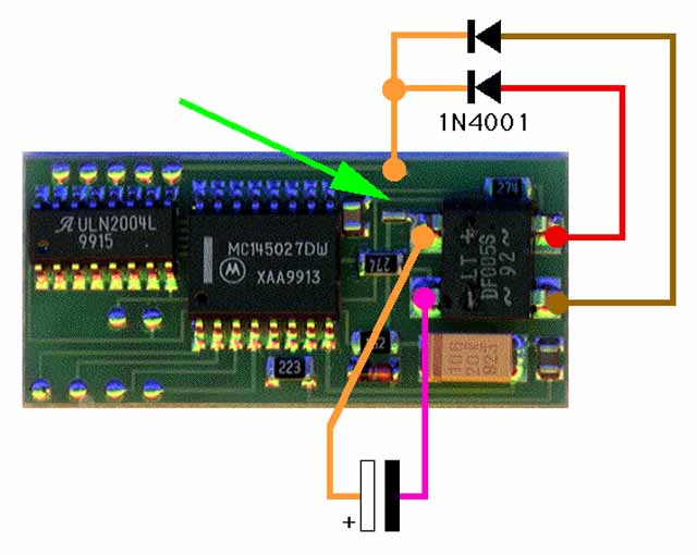
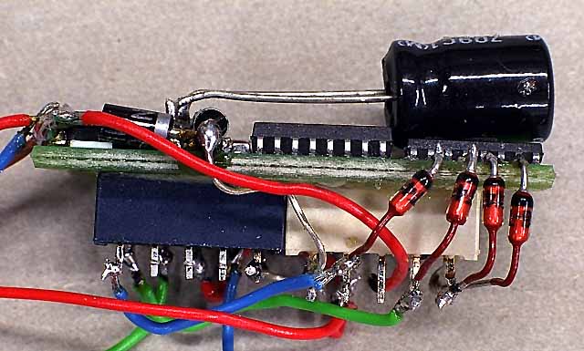
It is not possible to use this decoder in a car useful with its "amnesia". I was looking for a solution to buffer the chip. A capacitor behind the rectifier will do this, like shown at the graphic. First the zero ohm resitor must be removed (green arrow), otherwise the buffereed energy will be lost to the function outputs. Before making this photo, the resistor with the number 000 was removed. This "bridge" supplies only the function outputs. With two diodes 1N4001 I rebuild the positive part of the rectifier and connected it with one of the soldering pads of the removed resistor. Now the capacitor is only connected to the two chips.
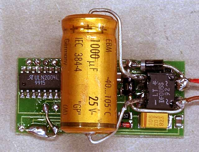
The photo shows the decoder after the modification. I placed the diodes around the rectifier, but the capacitor was eoo big to hide. A 1000 uF capacitor buffers the memory of the chip for approx. 15 seconds. This is enough for biggest contact problems, but if the power is off for a while after a derailing, the memory is erased. The c96 from Maerklin is bufferd for several days, but it costs much more. With a smaller 220 uF capacitor it is possibile to buffer the decoder up to 1 second.
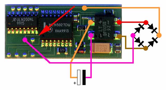
There is a second possibility to lower the consumption of power. The circuit between the rectifier and the IC ULN2004L must be cut (red arrow). Instaed to rebulid with two diodes a part of the rectifier, it is easier to solder a second rectifier onto the other. Like shown in the graphic, only the inputs of both rectifier are connected together. One positive wire leads to the soldering pad of the removed zero resistor. The negative wire leads to the soldering pad of the adressing pads near the IC. Now the capacitor has only to buffer the MC-IC and can be smaller.
The decoder is alraedy for switching interior lights with direct connected bulbs, but this not a good solution. The maximum output is limited to 1000 mA and this is just enough for short passenger trains. It is possible to use LEDs but this yellow light doesn´t look realistic. Besides a second backwire to the decoder is needed to have a flickerfree light, but the Maerklin power couplers have only one contact.
An another alternative is to operate with relay. There are two versions of relay. The relay with one coil is closed until the power is on. While a contact problem the relay will switch off. If the power for a short time lost, it is no problem, but after a longer time the relay will not switch on again, because the buffer is empty. It is neccessary to reactivate the function on the 6021 again. It is possible to lead the digital power with its positive and negative waves through the contact of the relay. By this no extra backwire for flickerfree light is needed and the weehls of the cars can be use for ground. I had rebuild my Maerklin control shuttle car in such a way.
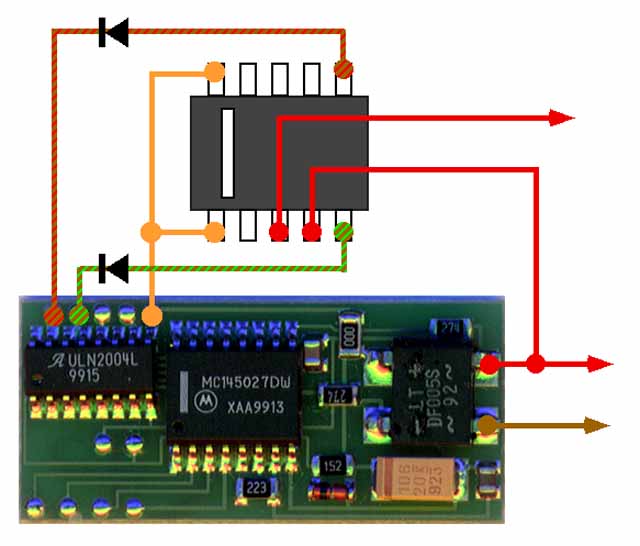
Using relays with two coils, only two functions are available, because two function outputs are needed to switch such a relay. For an example the relay will be closed with f1 and opened with f2. The red wire from the pickup shoe lead thorugh the contact of the relay to a passenger car. The white line on the top side of the relay is important. It is the same relay like the Maerklin 7244, Viessmann 5552 oder Voelkner 014-064-422. The graphic shows how to connect a relay to the function outputs f1 and f2. It is not dangerous to switch on f1 or f2 for a longer time, because the relay has a protection, nevertheless it is better to activate the f-functions only for a short time. To switch a relay needs only 0,1 seconds, but this is not possible while pressing the buttons at the 6021, but 0,5 to 1 second is a good choice. It is NOT ALLOWED to press f1 until f2 is on or reverse. This can damage the relay.
I think the solution with the "two-coil-relay" is the best way. Two contacts are enough for switching the interior light and to change the top light on a shuttle train between red and white. Using relays it is unnecceary to buffer the decoder, because the function outputs are switched on for a short time only. The photo shows the decoder with two relays and a smaller 220 uF capacitor.
Some of these decoders were deliverd with a failure. Instead of the 270 k ohm resitors (number 274) only 220 k ohm resitors (number 224) were mounted. Besides the IC had the number 2004L 9849. After mounting the other resistors, the decoder works well.