The loco decoders are only desinged for installation authorized Maerklin Digital dealers. Often the dealer has not time, wants to much money for the retrofitting, or he is not able to make some speacial installations. If one retrofittes the decoder by oneself and the decoder has a malfunction, it is impossible to send the hole locomotive to Maerklin. Also it makes a lot of work to remove the decoder. It makes sense to proof the decoder befor installing. I want to build such a decoder tester with simple components. As I saw the layer of the relay 7244 with its 10 connectors, I noticed that it are exactly enough for testing all functions of a 60901/2 or 90960.
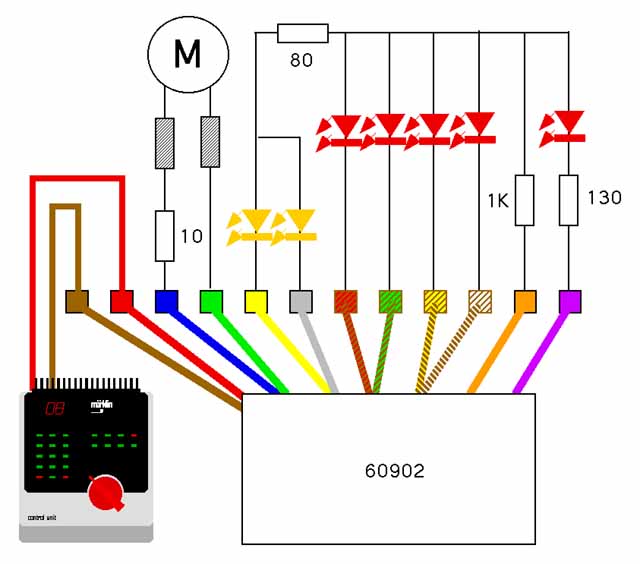
As seen in the wirering diagram, the red and brown wires from the control unit were soldered to the left connectors. An old LFCM motor with HAMO stator from my V100 is linked to the next two plugs. To make that the regulation works better, I soldered a 10 ohm resistor before the two coils. It is possible to check motor outputs of the decoder with simple LEDs, but with the connected motor I am able to proof all speedlevels and the potentiometers of max speed and acceleration/breaking delay (including f4 of the new decoders). The mechanical link of the motor with the wood board is quite easy. I glued the stator with the magnet onto the board.
The two most left connectors are used by the orange and the purple wire. I use LEDs to light and so a 1 kilo ohm resistor is needed. The 130 ohm resistor is needed, because without ist, the other LEDs are not working correctly. I think the reason ist, the purple wire ist directly connected to the diodes on the decoder and the other functions wires are connected to the 701.22 chip. The electrical power uses always the way with less resistance. After connecting the decoder, the most left LED is on. This says only, the decoder has power. The next 4 light diodes indicate the functions f1-f4. The normal 60901/2 has only f1 ans f2, but the 60960 has also f3 and f4. In the middle are the connectors for the yellow and the grey wire (function f0). For this function I took yellow LEDs. Its internal resistance is different, so I need an additional 80 ohm resistor. Without this, the red LEDs are going dark if I switch on f0. On a reproduction maybe other resistors are needed.
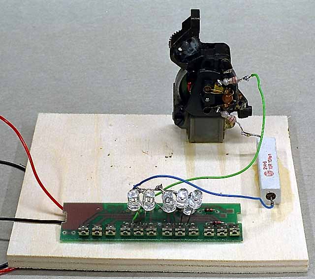
I was able to build a decoder tester with simple components. Of course it looks not pretty, but it works. It must not be a Maerklin motor to test the decoder. A simple DC motor do the same. Now it makes more fun to rebuild locomotives to digital, as I know I install a well working decoder.