The decoder 60902 is the successor of the decoder 6090 It has the funtion f0 which works in dependency of the driving direction and two auxiliary functions f1 and f2. The function f4 disables the delay. The color of the wires:
red = pickup shoe (power/data)
brown = ground (power)
blue = motor
green = motor
grey = front light function f0 (negative DC)
yellow = back light function f0 (negative DC)
orange = back conductors for all functions (positive DC)
brown/red = function f1 (negative DC)
brown/green = function f2 (negative DC)
brown/yellow = function f3 (negative DC)
brown/white = function f4 (negative DC)
purple = electronic ground (negative DC)
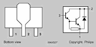
NPN transistor BST52 (SOT89)
Resistor 3R9/0,25W (SMD1206)
Resistor 47K/0,1W (SMD0805)
Normally the decoder carrys the transistors BST51, but it is hardly to get. I use often the BST52, but the BST50 works too. The difference is only the maximum voltage:
Collector-base voltage (open collector):
BST50 "AS1" max. 60V
BST51 "AS2" max. 80V
BST52 "AS3" max. 90V
Collector-emitter voltage (VBE = 0):
BST50 "AS1" max. 45V
BST51 "AS2" max. 60V
BST52 "AS3" max. 80V
Collector cut-off voltage (VBE = 0):
BST50 "AS1" VCE = 45V
BST51 "AS2" VCE = 60V
BST52 "AS3" VCE = 80V
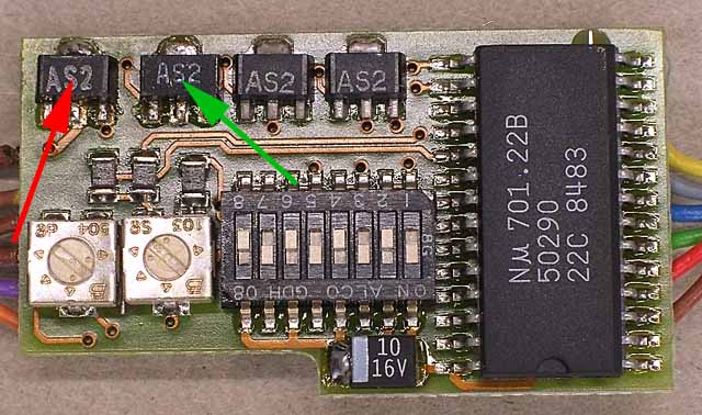
First I soldered the transistors onto the topside of the decoder. The soldering pads are already tin-plated, so the pieces can be soldered at once. To add the function f3 to the 60902, the transistor on the right must be soldered (green arrow), the left one ist needed for f4 (red arrow).
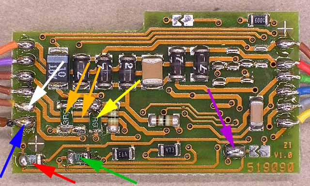
Some resistors must be soldered to the bottom side of the decoder. The function f3 needs the 47k ohm resistor (green arrow) and the 3.9 ohm resistor (yellow arrow). At last a wire must be connected (white arrow).
To add the function f4 also a 47k ohm resistor (red arrow) is needed. To solder a 3.9 ohm resistor there are two solutions (orange arrows), but it is the same, because the pads are connected together. Additional a special soldering pad must be bridged (purple arrow), to make a connection between the 701.22 and the new transistor. Simultaneously the option to switch off the delay is terminated. After soldering a wire (blue arrow), a bulb or another consumer can be connected.
The 3.9 ohm resistors for the functions f1 and f2 has a round body. I got only some flat resistors SMD1206. The maximum power capacity ist lower, but strong enough for the most functions. It is possible to double the power capacity by soldering one 8 ohm resistor on top of an other 8 ohm resistor. At the function f4 it is possible to solder the two 8 ohm resistors side at side. The maximum output of every function is 200 mA, but all together not more than 400 mA. The maximum output of the hole decoder, including the motor outputs and function f0, is 1100 mA.