Locomotives need to be equipped for digital control. While there are some cheats to run analogue locomotives digitally, they will not be the subject of this text. Maerklin offers several different decoders:
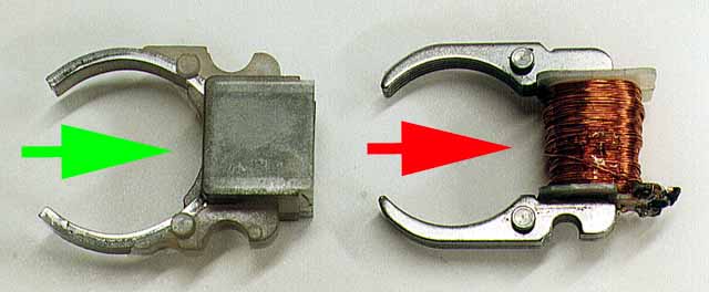
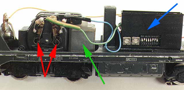
First, the c80 should be pointed out. This Decoder is meant for so-called universal (AC /DC) motors. These motors can be recognized by the coil on the stator or rotor housing (red arrow). Pure DC motors, such as the HAMO versions in many locomotives, have a stator with permanent magnets (green arrow). The c 80 Decoder, measuring 36 x 21 x 9 mm, has a bank of 8 DIP switches to set the digital address (1...80). Changes in running direction are initiated electronically, rather than through an electro-mechanical relay as it used to be the case. The integrated memory retains information about the last used speed and direction for some hours after the power has been shut off. If after several hours of shut down this information is lost, the decoder resets to forward direction, driving position 0, lights off. The decoder has a selectable auxiliary function to control lights or similar items depending on the running direction, with a maximum load of 2 x 0.2 Amp.
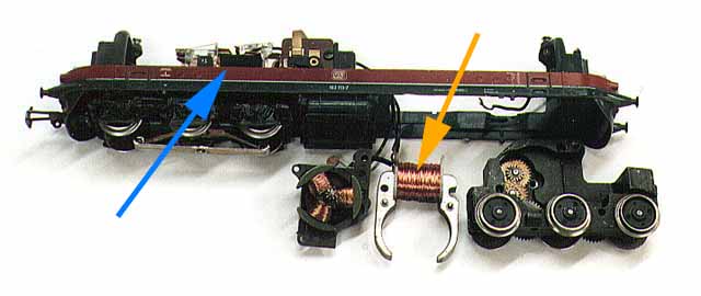
First the mechanical or electronic switch to change the travel direction has to be removed from the locomotive (blue arrow). The decoder will have to be mounted in its place. In newer locomotives with electronic switching, the decoder can be wedged into the same mounting plate, in lieu of the switching circuit board. The red wire of the c80 is connected to the pick up shoe and the brown wire is the ground. Thus the supply of current and information to the decoder is established. The black wire is soldered to the induction coil of the engine and the other side of the throttle is connected to one of the brush links. The blue and green wires are soldered to the field coil of the stator(orange arrow).
The gray wire is connected to the bulb for the front lighting and the yellow wire to the bulb for the rear lighting. Particular attention must be paid that neither of these cables touches the ground, else the decoder will be destroyed. Even the light bulbs should be checked for short circuits. The locomotive is now ready for a test run. In case the rear lights are on while driving forward, the red and blue wires on the stator need to be switched. The preferred forward running direction, with nearly all locomotives, is with the pick up shoe ahead.
If everything is soldered correctly, the exiting moment has arrived. First, I always check the light function. If this does not work, I immediately re-check everything! A decoder burns up quickly. Whoever expects the locomotive to start moving slowly after sending it drive position 1 through the computer, will be disappointed. The engine will just hum. Even with drive position 2 and 3 most locomotives will not start moving; at best they jerk a little. Then, suddenly, at drive position 4 they start racing away at an unrealistic speed. Reasonable shunting is hardly possible with a c80 and a constant rate of speed is nearly unattainable.
I once had a locomotive that drove about 2 meters at drive position 3 and then stopped and just hummed. If I accelerated from drive position 0 to position 4, the locomotive ran at nearly constant speed of 60 km/h (scale 1:87). But if I slowed from drive position 6 to position 4, the locomotive would run at 80 km/h. Further problems exist on inclines, where the speed setting must be increased by several drive positions, to avoid an unscheduled stop of the locomotive. The opposite is true for down hill drives; here the locomotive has to be slowed down by several drive positions, to avoid excessive speed and, as soon as the track levels out, the speed needs to be increased again. The cause for this behavior is a missing load control. Once the motor receives power, the rotor starts turning. Through the interaction between the magnetic field of the stator and the coils of the rotor, an induced current is produced that flows back to the decoder. By analyzing this current, it can be determined if and how quickly the rotor turns.
This can be accomplished with the decoder c90. After sending drive position 1, the rotor will initially not turn since the decoder supplies too little current. Actually, it is not too little current, since the voltage with the pulse width control system always remains the same, regardless of the throttle position. Rather the width of the pulse packets is too small to move the rotor. Since the rotor does not turn, no induced current is produced and flows back to the decoder. The decoder notices that and widens the pulse packets sufficiently to cause the rotor to turn, thus producing an induced current which is reported back to the decoder. This induced current signals to the decoder that the locomotive is running. If the induced current gets too high, the decoder adjusts the width of the pulse packets accordingly. Through these continual adjustments, the motor can be kept at a constant level of revolutions. At drive position 1 the locomotive will run at approximately 10 km/h (scale 1:87) without jerking or hesitation. Now shunting becomes a pleasure, but the tracks must be clean.
This load control system is especially effective in mountainous areas. On uphill stretches, the decoder adjusts until the actual speed of the locomotive corresponds to the set speed, even with heavy trains. When driving downhill, the decoder will decrease the width of the pulse packets to achieve the set speed. Thus it is possible for the layout operator to concentrate on running the trains, rather than worrying about locomotives that might be running too fast or too slow on a hidden part of the layout. De-railing trains due to excessive speeds on downhill stretches is a thing of the past. A further feature of the c90 is the adjustable top speed. This can be done through a potentiometer on the decoder. Using this feature, I calibrate all my locomotives to reach a top speed of about 100 km/h at driving position 10. Should a locomotive pass a signal showing Hp2 (slow speed), I simply transmit driving position 4 and the speed is correct. A further advantage is in the ability to double track different locomotives. This used to be impossible, since the different transmission ratios led to considerable variations in speed between the locomotives. Now it is even possible to use the second locomotive as a pusher BEHIND the train, without derailing cars in the middle. I have tested this mode of operation extensively and even in tight curves or across turnouts there were no problems.
Another feature is also available with the c90: The adjustable acceleration and breaking delay. Switching from a stop to drive position 10 causes normal digital locomotives to race away immediately. c90 locomotives on the other hand accelerate slowly, like the prototype, until they reach the set speed. To avoid problems with double traction, I adjust the potentiometers on the decoders to have equal stopping distances from driving position 2 to 0 for all locomotives.
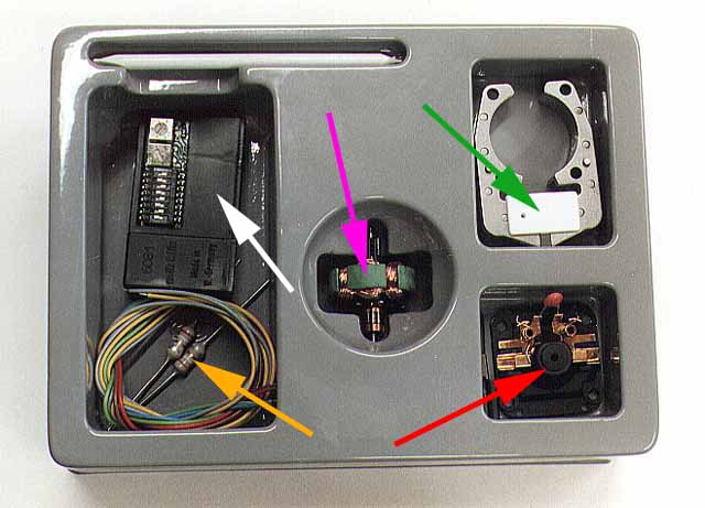
This change is somewhat more complex than the change to the c80, since the c90 only works with a DC motor. According to Maerklin, the change will only work reliably with the new drum commutator motors (DCM), but I have successfully done this change for the old large flat commutator motors (LFCM) as well. First to the DCMs. For this change, you require the 6090 Digital Propulsion Set. The set contains a motor housing with two brushes (red arrow), a stator with a permanent magnet (green arrow), a 5-pole DC motor (purple arrow), and the decoder with two choke coils 3.9uH +- 10% each (orange arrow).
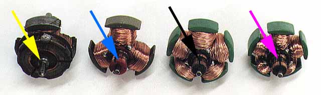
As with the change to the c80, the mechanical or electronic switch to alter the travel direction has to be removed from the locomotive. Then the motor housing has to be removed (unscrewed) and the 3-pole AC motor (blue arrow) must be exchanged for the 5-pole DC motor (purple arrow). Locomotives with catalogue numbers 35xx already have a 5-pole AC motor (black arrow), but this motor needs to be switched to the new DC motor with the smaller coils as well. The existing stator with coils also has to be replaced with the new one from the 6090 set. Next, the choke coils have to be soldered to the engine housing. They not only suppress radio interference, but also protect the decoder against high frequency voltage peaks. The blue and green wires from the decoder are soldered to the choke coils. The remaining decoder wires, except for the black one are identical to the c80.
6090 retrofits are recommended by Maerklin and more about it can be read in the book Einstieg in Maerklin Digital die Mehrzugsteuerung (0308). These changes can also be done through a Maerklin dealer. Changing older locomotives with LFCM is more of a problem. Many dealers are of the opinion that these locomotives should only be changed to the c80, because the 5-pole rotor is too small. However, this is not necessarily the case, as the example of the 3722 demonstrates. This particular locomotive is only available with LFCM. I have changed two of these old LFCM locomotives and the 3-pole rotor starts somewhat jerkily from a stop, but the differences are insignificant. The adjustable acceleration and breaking delay and the load control work just as well. Just the motor sounds a bit rougher. LFCM were developed as AC motors, i.e.: two coils that are wound around the stator produce the magnetic field. Having AC flow through only one of the coils causes changes in the rotational direction of the rotor. However, this is not possible with regular DC.
For a c90 decoder to control a LFCM correctly, the motor must be converted to DC. And naturally, the stator included in the 6090 set wont fit. Maerklin has also produced some locomotives with DC motors under the name of HAMO. These motors use a stator with permanent magnets and they can be ordered as spare parts. There are two versions: The large stator, as shown at the beginning of this text, for changing the LFCM and also a smaller version for small flat commutator motors (SFCM). The SFCM rotor (yellow arrow) can be found in the 515 Akkutriebwagen. It is less suitable for use with the c90 decoder, due to occasional problems during motor start up. While the 6090 motor isnt any larger, its magnets are considerably stronger than the ones of the HAMO stator for the SFCM; they are actually even stronger than the magnets of the HAMO stator for LFCM. The only exception is the LFCM stator in the 3722 (E94) that uses two very strong magnets of the type 7558.
First the mechanical switch to change the travel direction has to be removed from the locomotive and the universal stator has to be replaced with the HAMO stator (green arrow). Rotor and motor housing remain, but if necessary, the motor needs to be cleaned and the brushes replaced to avoid unnecessary sparks. Before mounting the rotor into the transmission housing, I lubricate all fast running (and only these!) gears with Robbe Teflon grease. Too much lubricant on slow running gears near the driving wheels, migrates quickly and ends up on the rails. Rotor axles and bushings in the transmission and engine housing also need lubricating. I stopped using the Maerklin oil since it is very thin, provides poor lubrication and does not adhere to the parts in the motor. While I was still using this oil my tracks became so slippery that I had problems starting heavier trains on level ground, not to mention inclines, of course.
After the motor is assembled it can be quite hard to turn it over by hand. The strong, permanently active magnetic field causes this. Nevertheless it should be possible to turn the motor by hand smoothly and without any jerking movements in the mechanism. As described before, the decoder wires should now be soldered on and you should end up with a locomotive that looks similar to the one in figure 4. In this picture, the decoder (blue arrow) is mounted above the chassis with double-sided adhesive tape. The plastic housing is open opposite the DIP switches and potentiometers. In the same location are transistors that can get quite hot during operation and the opening provides good heat dissipation. Also visible are the new copper contacts, the brush (red arrow) and beside it the HAMO stator (green arrows). On locomotives that are older than 10 years, the light bulbs must be replaced, since the old ones will be too bright and too hot. This is due to the higher voltage under digital power and new light bulbs are modified for use on this system. Before the first test run takes place, the wiring should be checked again. The exits for the various functions will self-destruct, if the yellow or gray wire touches ground. A short-circuit, caused by a defective light bulb, once destroyed a decoder.
First the DIP switches on the decoder have to be set for one of the 80 addresses. A good sign is if the locomotive is on the track and does not go up in smoke or starts racing away after the power has been turned on. First I switch on the lights. Due to the memory loss in the decoder after a long shut down, the locomotive should reset to the forward direction with the pick up shoe ahead. In this case the light bulb connected to the gray wire should light up. Steam engines are an exception, since it is clearly visible in which direction forward is. This rule is valid for all locomotives that are factory-equipped with a decoder. In case the lights do not match the running direction (e.g.: the rear lights are on during forward running), the blue and green motor wires need to be switched.