On page 5a Märklin Loks I described how to modify a Maerklin locomotive for digital operation. The c90 decoder provides excellent driving properties. With the new drum commutator motors (DCM) it is sufficient to install the 6090 propulsion set, by changing the stator, rotor and motor shield. Older locomotives can be modified for the 6090 with an HAMO-stator, by changing the motor to a DC motor.
Nearly all manufacturers use exclusively DC motors for their locomotives, yet it is possible to acquire so-called AC-models from them. These engines have the regular center-pickup shoe and a slightly modified wheel set, so they don't derail on Maerklin rails. In addition they have a switching relay to change the driving direction. Aside from further differences in the transmission, these locomotives generally exhibit a driving behavior that is just as good as the Maerklin originals. Would it be possible to equip these locomotives with a c90 decoder? Yes, it is! However, depending on the chosen model, there will be a considerable amount of work involved. The Roco locomotive of the series 110, 140, 141 and 150 are fairly simple to change. Since all these locomotives have pivoting suspensions, they are quite safe from derailments, even at high speeds; something that is not always the case with steam locomotives or older models with separate front axles.
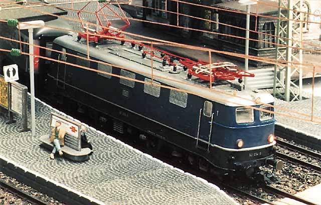
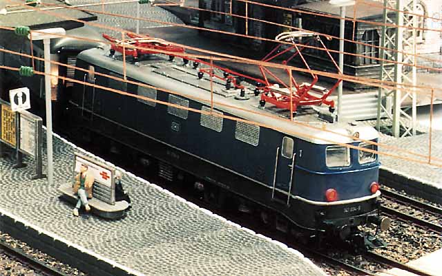
My choice was the multi-purpose locomotive of the series 141, since the Maerklin model from the 50's is no longer state of the art as far as detailing. Even Maerklin is now offering this locomotive only under the Hobby assortment. In addition, the Roco locomotive does not only provide for a simple change of lights, but also has red rear lights, as can be seen in the photographs.
First it is necessary to spread the plastic housing at the bottom and to remove it upwards. Then the circuit board with the switch for changing the driving direction needs to be removed. In the 141, this switch is above the pivoting suspension, where the worm gear is in the DC version. For this reason, only 2 axles of one suspension section are propelled in the 141. With the 110 or 140 series, this switch is underneath the locomotive, between the two pivoting suspension pieces and consequently both suspension section are propelled. If the eight-pole connector on the main circuit board is disconnected, the switch is for all intends and purposes removed.
As opposed to the decoders from Lenz or Uhlenbrock, the Maerklin c90 decoder cannot simply be put in place of the switch since it is too large. Nevertheless I recommend the installation of this particular decoder because it enables the locomotive to drive at extremely low speeds.
Because Roco locomotives have a plastic housing, the frame must be build quite massively and thus there is little space available inside the locomotive. The longitudinally installed center motor adds to the problem. To create room, I removed a piece of the circuit board above the motor. This will not work for all locomotives, since some of them have the bulbs for the illumination of the front in this space. I normally do not buy these locomotives, because there is little light coming to the front, due to the long and often bent lighting conduits.
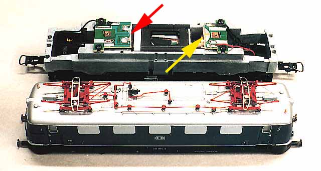
I cut the circuit board just behind the spring metal sheet connections for the motor (red arrow). For my first conversion, I did cut off more and then had to solder the wires directly to the motor connections. The second cut was made at a distance of about 4-cm (yellow arrow). In the photograph it is easy to recognize how much room is required for the decoder. Great care must be taken that the motor connections do not touch the frame.
If this should happen, the power transistors of the decoder (green arrows) will be destroyed immediately. If one is capable of accurate soldering, it is well worth to replace these, but in most cases the main processor 701.13 (violet arrow) is damaged as well. The same is valid for the transistors by the function exits (orange arrows) that should control the lights in this case.

To avoid a short circuit between the back of the decoder and the motor, I glued two strips of insulation to the motor and the frame. That might sound primitive, nevertheless it proved to be quite effective. These two strips also provide some support to the motor, which is now sitting loosely in the frame. Prior to the modification, the circuit board pushed down on the motor and thus kept it in place. Next I set the decoder address, since that won't be possible later on because the decoder will be attached with an adhesive strip (see photograph). The two potentiometers for the regulation of the top speed and the acceleration and stopping delay, I left free. This way of mounting has proven to be effective and thus far I have not had any problems with it.
As already known, the red wire of the decoder gets connected to the pick up shoe and the brown wire to the frame or to the black wires of the wheel take off. Since the wheel take off of both suspension pieces used to be connected on the old circuit board, this should now also be done with additional wire. While everything will work without this connection, it does increase the stability of operation if all four axles have electric contact to the rails. Care must be taken; that the ground connections on the circuit board have contact with the frame, else the light won't work later on.
I solder a choke coil with 3.9 uH to each of the contact points that lead to the motor (red arrows). These choke coils are included with the 6090 set. They serve not only to avoid radio interference, but also protect the decoder from electrical spikes. The other side of the coils is connected to the blue or green (resp.) wires of the decoder. The capacitor that is already present on the circuit board should not be removed, since it also serves to eliminate radio interference.
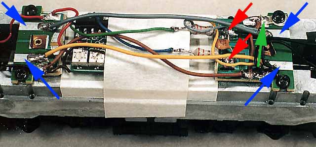
Lastly the light connections. Many Roco locomotives do not have sockets for the bulbs, rather they are just stuck into holes in the frame. Pieces of sheet metal press against them from the top, once the plastic housing is installed. First one must check that these springs are not bent. Should they touch the frame instead of the bulb, the function exit of the decoder will be destroyed. The outer ends of the four springs press onto the four bulbs (two red, two white), while the inner ends make contact with the appropriate blank areas of the circuit board (blue arrows). The yellow and gray wires need to be soldered there in such a way, that depending on the driving direction of the locomotive, three white lights are on to one side, while two red lights are on to the other side. As can be seen on the photograph, the two longitudinally opposed solder areas need to be connected with wires, since by now the center part of the circuit board is missing.
On this picture I also mounted a solder contact underneath one of the circuit board mounting screws and soldered a ground wire to it (green arrow). Due to this connection, the light flickers somewhat. Meanwhile I soldered a diode to the mass and a diode to the pick up shoe cable. (see also page 15: Neue Loks). Because of this, the frame is now "decoder positive" and the lights are flicker free.
The locomotive is now practically complete and should run without problems. If it starts to race away, immediately after it is put on the rails, it's already too late. In this case, one of the motor wires touches ground somewhere and the decoder is destroyed. Even for me, this is one of the most thrilling moments. After destroying a decoder, one tends to work more carefully.
There were no problems rebuilding this locomotive. I was afraid the decoder would not fit, since in the 141 there is no additional room in the form of a "roof hood" as is the case with the 110 or 140. But the housing did fit well after the re-build. Since I set the potentiometers for speed and acceleration / breaking delays to a medium setting, the locomotive starts up gently after receiving instructions for speed setting 4. Due to their construction, Roco locomotives are quieter than the ones from Maerklin. Also, a five-pole rotor is being used, which allows for jerk-free slow driving.
The case must be mounted to test the special functions of the decoder for the lights. It is extremely important to assure that all bulbs are in place and none of the contacts is bent, else one can purchase a new decoder right away. If one feels uncertain about these contacts, the spring contacts can be removed and the wires can be soldered directly to the bulbs.
Even if the lights are working, it can happen that they light up contrary to the driving direction. In this case the green wire leading to the motor has to be swapped with the blue wire. This is much easier than to re-solder all the lighting wires.