Maerklin Shuttle Control Car with c96
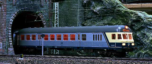
For my first shuttle train, I choosed the Maerklin control car 4257. It has a pickup shoe and changing front lights and looked like an already supported product. The description in the catalog is pushing by a loco three white lights are to see at the front side. The photo beside shows light yellow lights, but it seems to tolerable. While testing the control car the first time on my layout, I was very disappointed. The white lights shined in a dishusting dark yellow color. I may be ok for a old steam locomotive or another old style loco, but this is a modern control car. My opinon is that Maerklin economize the wrong things, by using LED instead bulbs.
A microswitch between the wheels changes the lights while changing the direction. In the beginning it works good, but pulling the car uphill the red lights became dark after stopping. Even sometimes the lights changed to yellow. After a while the microswitch worked unreliable, often only the red lights were on, even on flat tracks.
After installing an interior light and a changing front light to my Roco control car, I tried to do the same with my Maerklin control car. This shuttle train is short, only two cars long, and I want to use a c96 function decoder. Every output can serve up to 200 mA and this is enough for short trains. For long trains I prefer the combination k73 (6073) with relay. This can switch max. 2500 mA.
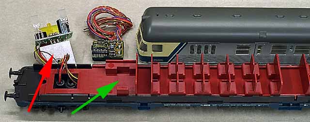
First I had cut a part of the interior with a Dremel and a cutting wheel, to have enough space for the decoder. I pasted a holding device and the c96 decoder into the baggage room (green arrow). As usual I connected the red wire to the pickup shoe and the brown one to the wheels. This purple wire is unused, so I had cut it off directly at the decoder. The outputs f1 and f2 had more power, so I used both for the interior light. I laid the brown/red wire under the interior to the electric coupler. This wire have to light only the second car. I installed an extra bulb in the baggage room and connected it with f3, to light it separate. I connected the electronic circuit of the frontlights (red arrow) to f4, so I can drive at daylight with front lights, but without interior light. I used always the orange wire as backwire to have a flickerfree light. The selfmade interior light (for more information take a look at selfmade interior lights) of the control car was connected to f2.

A problem was the second car, which is connected with the one-wire electric coupler 7319 to the conrol car. The power cames from the f1 output, but is impossible to have a flickerfree light, because the orange backwire ist missing. The electric couplers from Fleischmann with two connectors or from Roco with four connectors would be a good solution, but they are expensive. I installed under this car a ground wire to the wheels AND a pickup shoe. After that I rebuild the positive part of the decoder rectifier with two diodes 1N4001 to have the same electrical power as the orange wire has. This works like (solution with diodes) the flickerfree loco lights, but an additional pickup shoe is needed.
This is not a good solution and I tried to use a relay with one coil. It is a little reed-relay with one contact like:
MEDER DIP241A7212L
MEDER DIP242A7212D
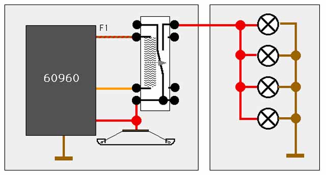
The second is a relay with a diode beside the coil to eleminate sparks, but it works also good without it. I had an old MEDER DIP24C9051L at home which has a two-way contact, but like shown in the circuit I use only one of it. The coil ist connected to the brown/red wire and the the orange wire. The red wire from the pickup shoe leads the digiral power over the contact to the electrical coupler. If f1 is switched on, the relay closes the contact and the second car has power. The digital power has negative and positive voltage and the bulbs were flickerfree, even they are connected to ground. A second pickup shoe is not longer needed.
To have a better interior light, I take four instaed three bulbs. Also I am able to couple more cars, because the power comes not directly from the decoder. The decoder hat to switch only the relay and a coil with 2 kiloohm resistor needs less power than one bulb.
Next I want to eleminate that u r i n e y e l l o w front lights. I bought at the electronic dealer Voelkner ultra small bulbs 1,2 V/12-15 mA 014-047-622. I want to exchange the yellow LEDs against white bulbs. The bulbs has nearly the same electrical data like LEDs but they shines brighter and hotter. I used a 130 ohm resistor to correct it. I started with the top light. I soldered off the LED and connected the bulb with a resistor. The bulb was smaller than the LED, so I sticked a straw into the hole of the car body. Now I modified the lower lights. I cut the outer pins of the two color LEDs for the yellow light. I soldered bulbs and 130 ohm resistors to this pin and to the pin in the middle. I glued the bulbs under the LEDs and the colorless body of the LED leads the light to front like a plastic light circuit. It looks fantastic. The LEDs were connected in a strange way together. If a bulbs goes dead, the other became brighter and after a short time, all bulbs were burnt out. In a short time I lost 7 bulbs. A second problem was the microswitch between the wheels, which change the lights. So I modified it again.
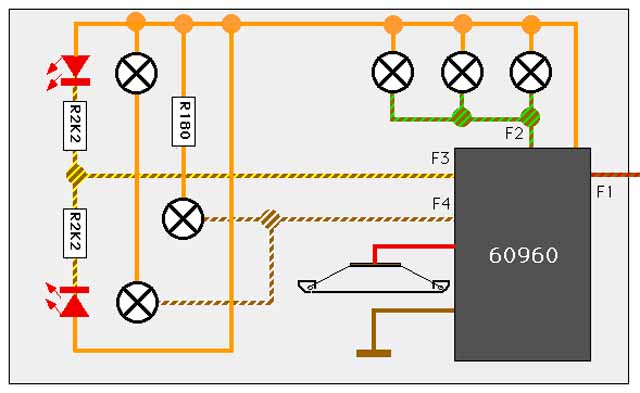
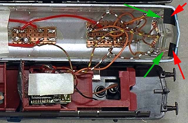
I removed the mircroswitch and want to change the front light while switching f4 (white) and f3 (red). My computer can do that, so I have not additional work while driving like users without computer. I removed the microswitch and the electronic components. Next I soldered off the two-color LEDs and cut off the unused yellow pins directly at the LEDs. I glued the LEDs into the front holes of the plastic car body. I connected both and 2,2 kiloohm resistors with the brown/yelloy wire of the f3 output. I removed the straw from the top light and glued a Maerklin bulb 61 00 40 into. This fits perfect. To fixed it, I put a drop solvent free glue onto the bulb. This bulb became got in digital systems, so I connected it to a 180 ohm resistor. Now it shines not so bright and is less hot. To make the lower bulbs less hot I connected both in serial to the brown/white wire of the f4 output . I glued the bulbs under the LEDs and the colorless body of the LED leads the light to front like a plastic light circuit (green arrows). To avoid that some light rays shines through the rift between car body and chassis, I glued some black paper onto the bulbs (red arrows).
The result is convincing, as the photo shows. After all the control car has not longer "french fog light". The front targetboard is not extra lighted, but the light rays from the top bulb are strong enough to iluminate it.